Rendering Wireframe in Houdini
Last updated on: 20 September, 2025
Introduction
“How do I render a wireframe in Houdini”? This question emerges on forums from time to time. With so many ways of reaching each goal in Houdini, it goes without saying that many answers to this question exist. How do we want the rendered image to look like? How much spare time do we have? Finding answers to this next set of questions has great impact on choosing the most suitable method. In this article we will find five of the most commonly used techniques of creating wireframe clay renders with short descriptions of their advantages, disadvantages, and quirks.
Unless noted otherwise, most methods use similar composition process. We usually need to perform two separate renders – one for the wireframe itself, and the second for shaded geometry. We then multiply together both images, preferably in a COP Network. In order to prevent the image output from having undesirable transparent pixels in place of wires, we should take care during multiplication as some techniques will render data into alpha channel of the image holding the wireframe. Excluding this channel from plane scope of Composite COP or Multiply COP usually helps to solve this problem.
As our model, I decided to use the cute squishy squab from SideFX, which I believe most Houdini users has learned to love.
Flipbook
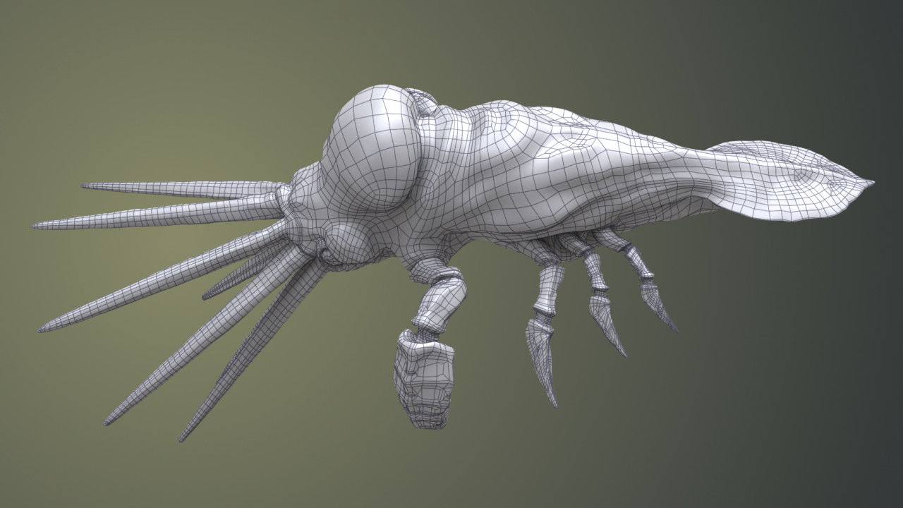
Flipbook wireframe render.
Many people regard this method as the most common and easiest to set-up and even the official Houdini documentation recommends it on its pages. Flipbook performs WYSIWYG renders of the viewport, which means that it will not only render active shading mode, but will also catch every marker, guide and visualizer that we have active at the time of rendering. It draws heavily from viewport settings although we can override some of them, like quality of anti-aliasing, camera shutter speed or f-stop, using Flipbook options. One of these options allows for overriding camera resolution, but not without some flaws when rendering image of resolution greater than viewport dimensions. In such case interpolation will occur and, as a consequence, the output will become blurry.
Unless our scene consists of meshes of high polygonal complexity or contains visual effects intended for rendering alongside clay wireframe render, Flipbook will render the output virtually instantaneously with speeds similar to viewport performance.
We might encounter a slight problem after restarting Houdini as this action will revert Flipbook settings to their defaults. It might not matter much if only frame range needs re-tweaking (by default Flipbook renders the whole timeline and usually we want to render only a single frame), but if we fancy some additional effects, like depth-of-field to name one, readjusting Flipbook settings after each restart gets old pretty fast.
All in all, I find Flipbook ideal for rendering wireframe of a finalized model, but not so convenient as a way of delivering regular updates on geometry topology.
Wren ROP
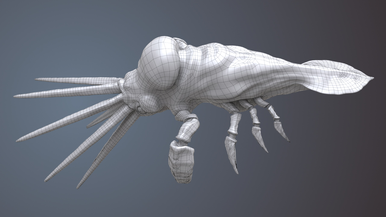
Wireframe rendered with Wren ROP. Line width is equal to 3 and is constant throughout object’s surface. Note dark homogenic areas on narrower parts of the model.
Artists call it Houdini’s wireframe rendering program, but if we attempt to render with Wren ROP for the first time in our lives, its output may baffle us as we will see that it yields an image of object’s outline instead of the usual wireframe. This happens because the program heavily relies on angles between faces and therefore, to visualize our mundane looking wireframe, requires appropriately prepared geometry. We can drop a Facet SOP at a point in our SOP network where we want the wireframe rendering to take place, then in that SOP, either set unique points flag to true, or enable cusp primitives and set their angle to zero. Finally, we move the render flag to this node or something downstream, go back to Wren ROP and render out our image. Much better, right?
We can adjust thickness of the wire by tweaking linewidth parameter in the Wren ROP or by creating a point attribute of the same name. Using the latter lets us emphasize some edges more than the others which results in nice aesthetics.
Even though we have wr_samples(xy) parameter at our disposal in the Wren ROP, a parameter responsible for the number of pixel samples during rendering, on my workstation it seems to have no effect on the final render (as of Houdini 17.5.258).
Apart from that, no other parameters influencing the quality of the rendered image appear to exist.
Therefore, to avoid aliasing we can render a higher camera resolution and then downscale the output.
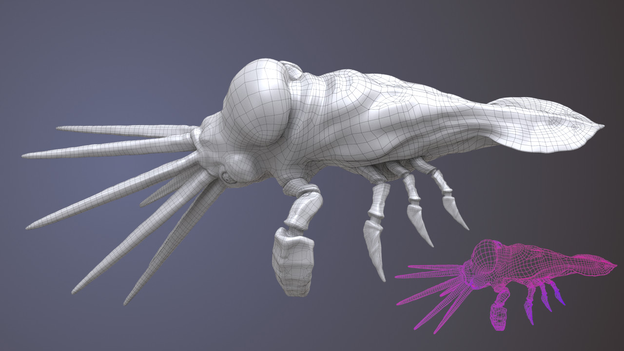
Wireframe rendered with Wren ROP. Line width is driven by primitive area. Bottom right corner: visualization of “linewidth” attribute.
Wireframe downscaling leads to a different problem. If a mesh contains areas of high concentration of smaller polygons (in contrast to their neighbors), or points of high valence, then after downsizing the image we might notice a tendency of wireframe clumping into dark or bright solid splats (depending on the color of our wireframe). None of the available scaling filters seem to eliminate it, but we can minimize the effect by varying linewidth point attribute depending on primitive area size or point valence. Measure SOP combined with Attribute Blur SOP will make the process easy, but of course we can also achieve the same with VEX or HOM.
Rendering speed of Wren ROP feels at least as fast as the Flipbook.
OpenGL ROP
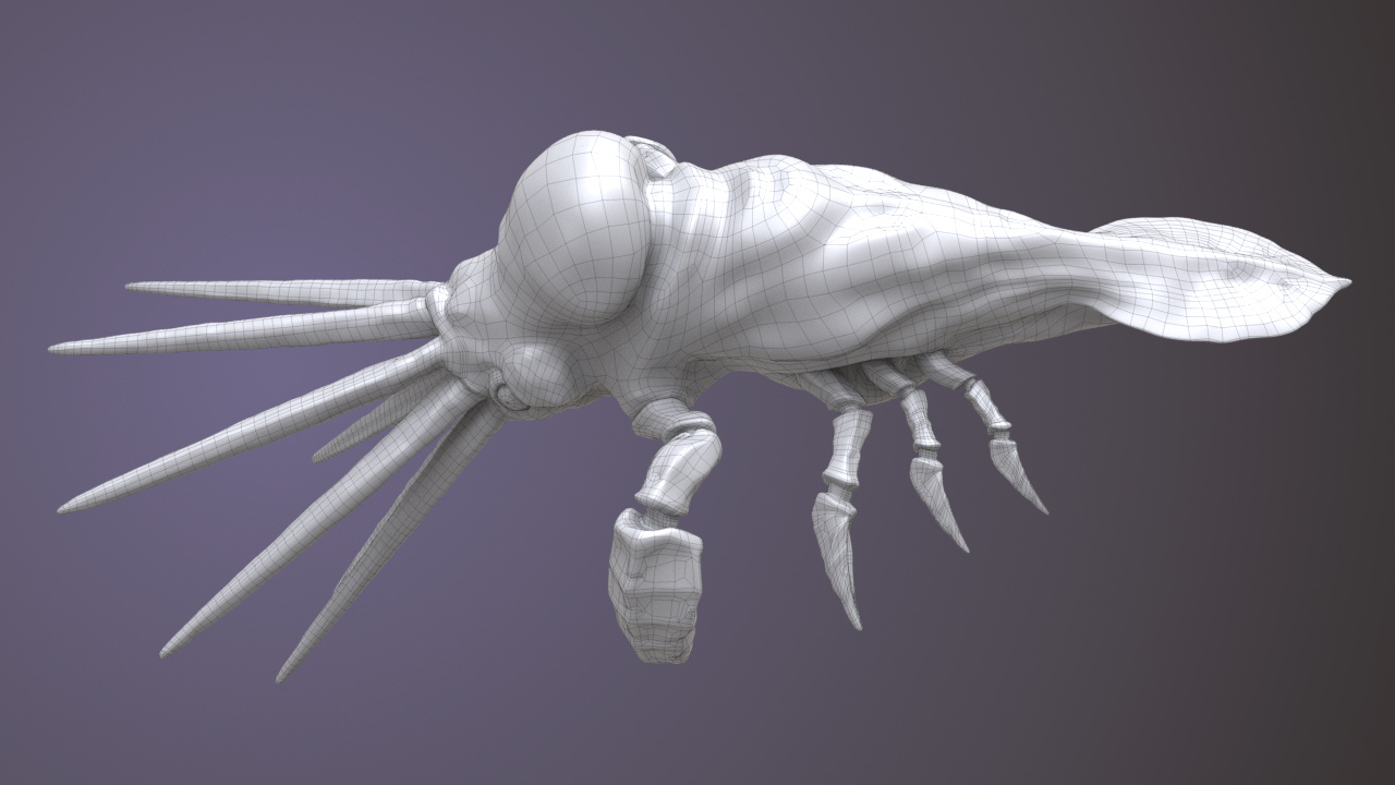
OpenGL wireframe render. Note how thin the lines are.
OpenGL ROP is a straightforward renderer that gives us similar results as Wren ROP, minus the ability to affect line width and the requirement of having to fiddle with face angles in order to render a proper wireframe. This ROP allows us to override some settings that we know from the viewport like anti-aliasing samples or shading samples, while for some shading modes it provides additional parameters for tweaking light or ambient occlusion samples or depth of field. Unfortunately, increasing anti-aliasing samples seems to have no effect on image rendered on my workstation.
To my knowledge, no special prerequisites or tricks to render wireframe with this node exist. We pick our shading mode (usually “hidden line”), set anti-aliasing samples (if AA works for us) and press the render button. In compositing we need decide how to resolve the problem with the color channel of the rendered wireframe because it will render in shades of gray. For example, we could ignore this channel completely and use wireframe alpha to drive multiplication of shaded render with a uniform black color. Or we could use Levels COP followed by Limit COP to increase contrast of the color channel and clamp it in [0, 1] interval, though I personally favor the first solution.
If AA fails to engage, then in order to get rid of wireframe aliasing we need to perform the same camera trick that we already know from the Wren ROP.
Wire SOP
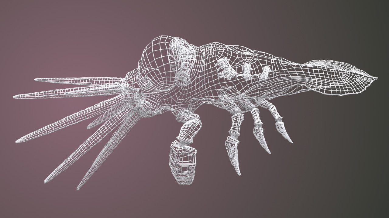
Wireframe rendered as physical geometry. Model’s primitives facing away from the camera (backfaces) are ignored by the renderer.
A unique method among the others because it cannot produce a rendered image all by itself. Wire SOP turns edges into straight polygonal lines and then sweeps a circular curve along them producing open or closed tube primitives. By setting round corners flag to true, we can tell it to insert a sphere primitive in place of each point of the geometry. Those spheres, inheriting the radius of neighboring tubes, create a perceptual impression of a continuous mesh despite severe fragmentation of the output geometry which contains the same number of separate tube and sphere primitives as the number of edges and points of the original polygonal mesh.
Output of Wire SOP brings similar impressions to a wire fence wrapped around an invisible solid object. And like with that wire fence, we can look through it and see wires on the other side, which we surely did not ask for. The remedy for this issue relies on Merge SOP, with which we simply merge the output of Wire SOP and our original polygonal geometry. To emphasize the presence of a wireframe, we can give it a different material that the surface already has.
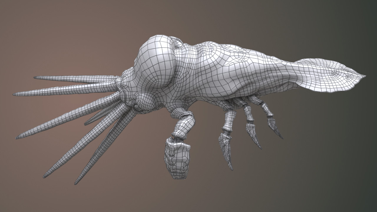
Wireframe rendered as dark tubes and merged with object’s original geometry.
If we want to produce an image of pure wireframe, but without the original polygonal surface, and at the same time to reduce the clutter that wires from the other side of the model generate, we can take advantage of
Delete SOP and its affectnormal flag.
This parameter enables removal of polygons that fulfill a specific condition. Among those conditions we can find a camerapath parameter, which accepts a reference to a camera object.
Once we provide it, Delete SOP will remove all polygons back-faces from the original object.
We then feed Wire SOP with our cleaned-up geometry, and as a result of this whole operation, we get a relatively uncluttered wireframe.
When using Wire SOP for wireframe clay renders and assuming that we have merged wire with original surface of the model, we can skip the compositor because the render already contains wireframe. Hence, render time will roughly equal time required to render the shaded geometry with some additional overhead caused by the presence of extra wire geometry generated by Wire SOP.
Custom Wireframe Shader
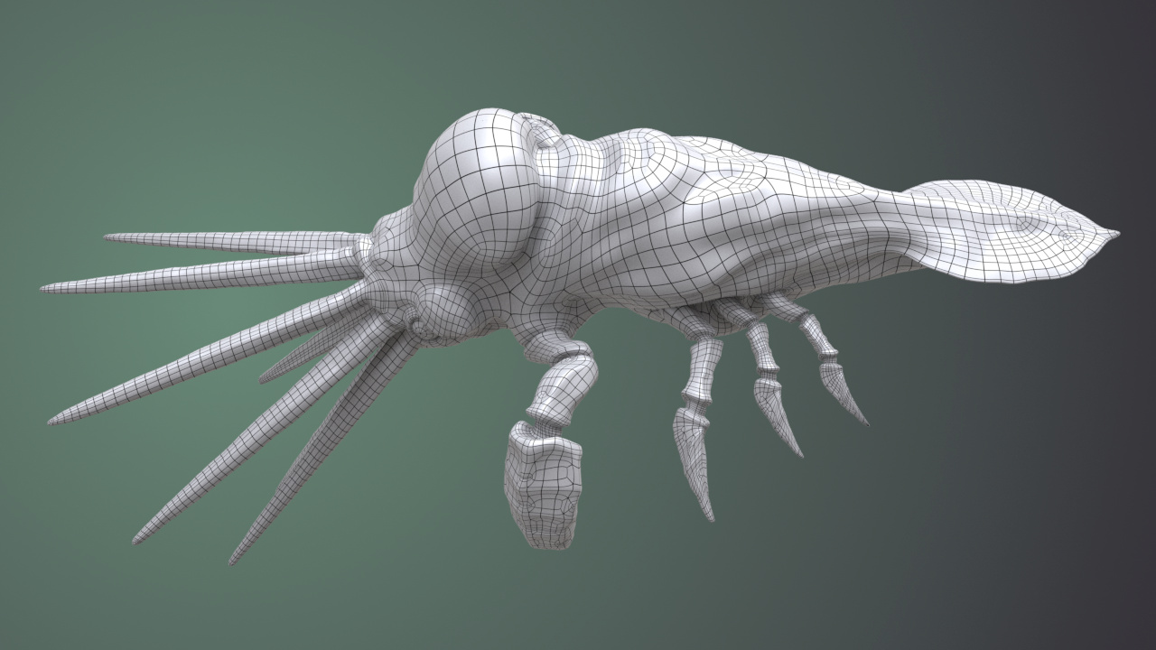
Wireframe rendered with a custom shader. Note the wireframe subdivision.
Using a custom-build wireframe shader has one major advantage over the other techniques mentioned on this page. It can render wireframe of a subdivided polygonal geometry without including edges generated by subdivision algorithm (we need to use “Render Polygons As Subdivision” flag for that, rather than Subdivide SOP). With a proper shader setup we can also render both: the wireframe and shaded model at the same time which saves us some time and processing power that we would otherwise need to spend on rendering both images separately and finally compositing them together.

An rough example of a basic wireframe shader.
The graph above demonstrates a structure of a basic wireframe shader that will allow us to produce wireframe image which we would then take into COP Net for compositing with clay render. By creating a shading layer from the Lighting VOP and dropping a Principled Shader into the network we could mix both layers together using alpha from the second Complement VOP (counting from the left side), effectively expanding the shader into one that renders everything in single pass.
MaterialX (Solaris)
Some time ago, Jonathan Mack from SideFX forum used MaterialX operators to implement a wireframe rendering solution described in NVIDIA’s “Solid Wireframe"whitepaper from 20071. It works with Karma CPU and XPU renderers, returns results similar to the custom shader described in the previous section, respects subdivision and sports customizable wire thickness.
Final solution that I eventually settled with, uses suggestions from another forum user who comes by the name EvilDuck.
He proposed utilizing component builder, physical polygonal curves converted from edges and pscale attribute to control the thickness.
I slightly expanded his solution by adding camera distance compensation, because the original method didn’t take this into account.
This makes the wireframe width constant, regardless of camera distance from geometry.
Additionally I decided to use MaterialX Unlit shader with AO multiplied in, instead of MaterialX Standard Surface.
You can download the demo scene file from this location.
Epilogue
Six methods, some significantly different from the rest, the other somewhat similar, but all of them lead to the same goal just with different routes. Deciding on which method we should use depends entirely on circumstances and subjective preference. After all we can encapsulate all techniques described in this article (except of the Flipbook method) into Houdini Digital Assets in order to conform to Houdini’s unwritten principle of building things once, and reusing them unlimited number of times later.
To speak for myself, in the past I fancied the custom material method, as it lacked weird quirks and because in my feeling it provided the most control over the appearance of a rendered wireframe. Nowadays, as I keep on moving to USD workflow, I plan on switching over to Mack’s MaterialX method.
Addendum
This post was my first attempt of writing in English Prime, so hopefully you won’t find any forms of the verb “to be” in its content apart of picture captions and this short addendum. Otherwise, it would mean that I failed.